
How to install a Bluetooth Module in Mini60 Antenna Analyzer
First open the analyzers case, then unsolder the powerswitch and antenna jack.
remove the 4 screws in the edges.

remove the pcb from the case
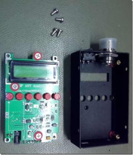
now you are ready to solder the BT-Module in place

the module is soldered with only 5 solderpoints to the pcb, solder a short wire from the BT Antenna
to the positive lead on the charging connector, this will act as a antenna jack for the BT antenna.
(i dont know if this is a good idea, but this is the way it is originaly done.
I dont know what happens if a power supply is connected here.)

and now the important part which is often forgotten when assembling the BT Module.
(This has also happend to some original Bluetooth MINI60)
Look for the holes/solderpads in the green circle and connect them with wire to the
back pcb where the hole/solderpad is in the red circle. This is the RX/TX connection
between the two pcb's.
(If both pcb's are not connected this way, you will not get any data via BT. There are
no other RX/TX traces between the pcb's. It is possible to establish a BT connection
with your Android/PC, but no data will be sent/received.)

could look like this

if everyting is well you are ready to run a test.
..... to be continued